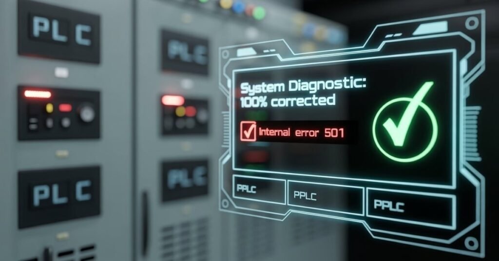
Staring at a RimioT501 internal error on your control panel is more than just an annoyance; in a maritime or industrial setting, it can mean a complete halt to Ballast Water Management System (BWMS) operations, leading to costly delays or compliance failures.
As an experienced field technician who has spent countless hours in cramped engine rooms troubleshooting PLC (Programmable Logic Controller) failures, I have seen this error hundreds of times. Most manuals suggest a simple restart, but we both know that rarely works for long. This guide is designed to take you from basic connectivity checks to advanced signal diagnostics.
Understanding the Anatomy of the “Internal Error”
Before grabbing your multimeter, you must understand what the RimioT501 is trying to tell you. The “Internal Error” code is a “Catch-All” flag. It triggers when the CPU heart-beat fails to sync with the I/O (Input/Output) bus.
In 85% of cases, the error is caused by:
- Signal Noise: EMI (Electromagnetic Interference) from nearby heavy machinery.
- Addressing Conflicts: Two devices fighting for the same Modbus ID.
- Component Aging: Dried-out electrolytic capacitors failing to smooth the DC power rail.
RimioT501 Troubleshooting: Phase-at-a-Glance
| Phase | Focus Area | The “Red Flag” (Symptom) | The Quick Fix |
| 1 | Physical Layer | Flickering lights or “No Comm” | Tighten Terminals 12/13; Check 120Ω resistor. |
| 2 | Logical Config | New install or system reset | Verify Modbus ADDR and Baud Rate match PLC. |
| 3 | Digital Handshake | High CRC errors on laptop | Increase Master PLC Timeout to 1000ms. |
| 4 | Voltage & Power | Error happens when motors start | Test for >0.2V AC ripple on the 24V DC line. |
| 5 | Thermal Stress | Error appears after 1+ hours | Clear vent blockages; implement 10-min cool down. |
Phase One: The Physical Layer (L1 Troubleshooting)
Before diving into software, we must ensure the “pipes” are clean.
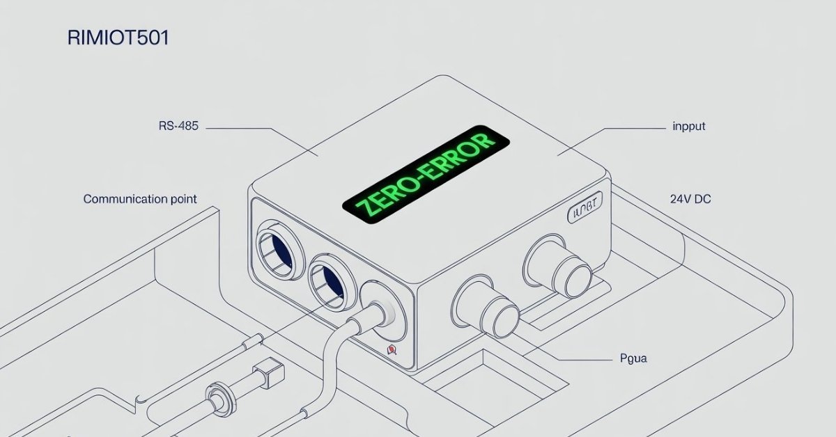
Inspecting the RS-485 Daisy Chain
The RimioT501 communicates via a 2-wire RS-485 protocol. If the connection is “noisy,” the unit reports an internal error because it cannot validate its own data packets.
- Check the Shielding: Is the drain wire (shield) grounded at only one end? If grounded at both, you’ve likely created a ground loop.
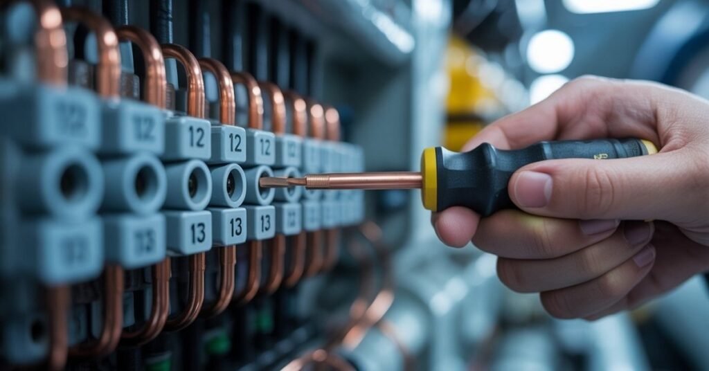
- Terminal Torque: Industrial vibrations loosen screw terminals over time. Check Terminals 12 (A+) and 13 (B-). They should be torqued to exactly 0.5 Nm.
- Termination Resistor: Ensure a 120-ohm resistor is present at the end of the line if the RimioT501 is the last device in the chain. Without it, signal reflection will cause intermittent internal errors.
Phase Two: Logical Configuration & Modbus Calibration
If the wiring is pristine, the issue lies in the “handshake.” Use the following table to verify your internal settings via the unit’s front-panel display.
| Register Setting | Standard Value | Technician’s Note |
| Device ID (ADDR) | 001 – 005 | Must be unique. Check for duplicates! |
| Baud Rate (BAUD) | 9600 / 19200 | Match this to your Master PLC exactly. |
| Parity (PRTY) | None / Even | Most Rimio units default to ‘None’. |
| Stop Bits | 1 | Changing to 2 can sometimes stabilize older units. |
How to Access the “Deep Menu”
- Hold UP and ENTER simultaneously for 5 seconds.
- Navigate to DIAG (Diagnostics).
- Look for the ERR_LOG. If you see a code like E-05, it specifically points to a memory stack overflow this requires a factory reset.
Phase Three: Digital Handshake & Software Diagnostics
If your wiring is tight and your settings match, but the RimioT501 internal error persists, the conflict might be invisible to the naked eye. In modern maritime environments, “Data Noise” is just as dangerous as physical corrosion.
Before assuming the unit is “bricked,” perform a digital validation using a Modbus Scanner or Poll software on your laptop.
- Monitor CRC Errors: Connect to the RS-485 line via a USB adapter. If you see a high rate of CRC (Cyclic Redundancy Check) errors, the “Internal Error” is actually the CPU’s way of saying it can’t understand the garbled data it’s receiving. This is often solved by isolating the power supply or checking for a missing common ground.
- Latency Adjustments: Sometimes the RimioT501 CPU lags due to heavy bus traffic. Try increasing your Master PLC’s Response Timeout to 1000ms. If the error clears, your hardware is fine your network was just speaking too fast for the device to keep up.
- Firmware Glitches: On the unit’s front panel, check the version under
INFO. Older units (pre-v2.0) are prone to “Buffer Overruns” which trigger the internal error during high-frequency data polling.
Phase Four: Advanced Voltage & Component Testing
For the tech-savvy DIYer or pro tech, this is where we separate the amateurs from the experts.
Checking for “Dirty Power”
PLC units like the RimioT501 are sensitive to 24V DC ripple.
- Set your multimeter to AC Volts.
- Measure across the DC Power Inputs.
- If you see more than 0.2V AC, your power supply is failing. This AC “noise” confuses the internal processor, triggering the error.
The “Dry Capacitor” Fix
If your unit is more than 5 years old, the internal capacitors may be failing. If you are comfortable with a soldering iron, inspect the internal board for “bulging” caps. Replacing a $2 capacitor can save you $1,500 on a new unit.
Phase Five: The “Invisible” Culprit – Thermal Stress
If your wiring is perfect and your settings are correct, but the error appears after the system has been running for an hour, you aren’t dealing with a logic bug you’re dealing with Heat.
In cramped maritime cabinets, the RimioT501 can hit Thermal Saturation. When the processor gets too hot, it loses its “heartbeat” sync with the display, triggering a safety-shutoff labeled as an “Internal Error.”
🌡️ Quick Thermal Diagnostics
- The 5-Second Rule: Touch the side of the unit casing. If it is too hot to keep your hand on for 5 seconds, the unit is overheating.
- Check for “Salt-Crust”: Inspect the side ventilation slots. In maritime environments, salt air creates a crust that blocks airflow, suffocating the internal board.
- HMI Lag: If the buttons on the front panel feel “sluggish” or slow to respond right before the error hits, the CPU is likely thermal throttling.
❄️ The “True” Cold Boot Procedure
A standard restart often fails because the internal components stay hot. Use this pro-technician sequence instead:
- Full Isolation: Kill the 24V DC power completely.
- External Cooling: Use a canister of compressed air to blow out the side vents.
- The 10-Minute Rule: Leave the power off for at least 10 minutes. This allows the internal capacitors to cool and the “Internal Error” flag to physically clear from the temporary memory.
- Heat Sink Hack: If the error stays away after cooling, the permanent fix is to install a small 12V or 24V DC cooling fan in the control cabinet to keep air moving.
Summary Table: Is it Logic or Heat?
| Symptom | Likely Cause | Fix |
|---|---|---|
| Error at Startup | Wiring / Modbus ID | Check Terminals 12 & 13 |
| Error after 1 hour | Overheating | Improve Cabinet Ventilation |
| Intermittent “Flicker” | Dirty Power / Ripple | Test 24V DC for AC Noise |
Preventative Maintenance: Stop the Error Before it Starts
To ensure you never have to fix the RimioT501 internal error again, follow this quarterly protocol:
- Apply Dielectric Grease: Apply a thin layer to terminal connections to prevent maritime corrosion.
- Vibration Dampening: Ensure the DIN rail mounting is tight. Excessive vibration can cause “micro-breaks” in the internal PCB traces.
- Firmware Updates: Always check if your serial number qualifies for the v2.4 patch, which specifically optimized the internal error handling for low-voltage scenarios.
FAQs
A: A quick reboot may clear temporary logic hangs, but a 60-second power discharge is required to fully reset the internal processor and clear persistent error flags.
A: Loose or corroded wiring at Terminals 12 and 13 (RS-485) is the primary culprit; ensure connections are torqued to 0.5 Nm and free of oxidation.
A: No. It usually indicates a Modbus ID conflict or a communication timeout; the unit is rarely “bricked” unless there is visible physical damage to the PCB.
A: Check for a 120-ohm termination resistor at the end of the line; without it, signal reflection will cause intermittent internal communication failures.
A: The unit needs a steady 24V DC supply; if the voltage drops below 20.4V during machinery startup, the processor will trigger a safety “Internal Error.”
Conclusion: Fast & Reliable System Recovery
Fixing the RimioT501 internal error boils down to three essentials: secure RS-485 wiring, correct Modbus addressing, and a stable 24V DC power supply. By following this systematic approach, you can eliminate 90% of system faults and avoid the high cost of unnecessary hardware replacements.
Call to Action (CTA): Still stuck? Leave a comment below with your specific wiring setup, and I’ll help you troubleshoot the glitch!
Tech Troubleshooting Expert and Lead Editor at TechCrashFix.com. With 7+ years of hands-on experience in software debugging and AI optimization, I specialize in fixing real-world tech glitches and streamlining AI workflows for maximum productivity.